Self-help recovery II

...how not to make a mistake during assembly
Here we summarize a basic list of mistakes to avoid when starting to install a ventilation system with central passive heat recovery (without a heat pump, reheating or cooling) yourself. If possible, always use the services of an expert (preferably an authorized designer) and installer. The article summarizes our personal opinions gained from several years of using the ventilation system with recuperation and, of course, also experience from several hundred of our installations, which we have installed on a turnkey basis throughout the Czech Republic over the past few years.
What is intake, exhaust, intake, exhaust air? Where is the muffler located? Take a look at the simple sketch in the following article - Recovery by self-help III ...how to buy from our eshop
How to proceed, before purchasing, how to ask for advice, read in the article Self-help recovery I. ...before installation
OUTLINE OF THE ARTICLE:
2) Intake and exhaust (exterior- unit)
3) Inlet and outlet (unit - interior)
1) Recovery unit
Position
Always install the recovery unit on a sufficiently load-bearing structure that does not transmit noise. Beware of wooden buildings!!!
A technical room, as far as possible from bedrooms and rooms, is ideal.
For the wall-mounted recuperation unit, it is better to keep the entire space from the floor to the ceiling.
Space for silencers and intake and exhaust bends is usually required for an under-ceiling unit . So if the technical room is not more than 3.5 m long in a given direction, then the installation will not be completely ideal and it may be worth considering another type of unit.
The recuperation unit cannot be installed outdoors (we don't know of any in the size for a RD that would allow this). The ambient temperature should be approx. 5-50°C (the exact range depends on the manufacturer). The ideal solution is if the ambient temperature of the unit is as similar as possible to the indoor temperature. Then neither the heat nor the cold, which we want to return, is lost through the walls of the unit. The body of the unit is of course insulated. It is therefore not suitable to install the unit on the ground if it is not part of the thermal envelope of the building or in an unheated garage. When installing in the attic, it is also necessary to consider the transmission of noise through the ceiling.
Preparation
Don't forget to drain the condensate and prepare the cabling (power supply, controller, internet, boost buttons, sensors, etc. - everything with sufficient reserve).
Make sure that the condensate drains freely , it must not freeze and cannot be forced in the opposite direction by e.g. water from the washing machine - i.e. use the siphon specified in the manual for the unit.
Never use the unit to dry a structure that is not perfectly clean and free of dust. There is a risk of permanent damage to it. Likewise, the basic units we offer are not suitable for ventilation of swimming pools, etc.
Have the unit connected and the system regulated by an expert with the manufacturer's certificate , you will avoid problems with possible complaints.
2) Intake and exhaust (exterior - unit)
The facade wall grid must have a sufficient flow area, corresponding to min. flow area of the pipe.
An exhaust directed to the roof ( roof header ) tends to be less economical than to the facade. It causes problems with condensate drainage (can be solved with condensation pieces ). On the contrary, in extreme winter it does not cause icing on the facade, and in the case of placing the intake on the facade, it is almost certain that the intake and the exhaust do not mix.
The blown air must not affect the suction. There are also combined (combined) grids on the facade, but they may not be 100% functional under bad weather conditions.
Choose the suction from the cleanest side of the house, world orientation does not play a big role. The unshaded south side presents a problem in the summer. In the case of single-family houses, suction on the roof does not belong (sewage ventilation, etc.).
It is advisable to install a damper controlled by a servo drive on the intake, but in areas with little wind, a non-return damper is also sufficient. The selection of damper and actuator must correspond to the type of unit.
If you do not plan to frequently turn off the system on the exhaust, install a non-return valve. Pay attention to the axis of the butterfly flaps and the UP position for super tight flaps .
If possible, direct the exhaust through a heated space. For units with a classic plate heat exchanger, which exhausts air with 99% RH, a large amount of condensate can immediately form when the pipes cool down.
The intake and exhaust branches should be as short as possible (material cost, risk of moisture condensation), so plan the unit closer to the exterior wall.
The intake and exhaust pipes must be perfectly insulated - no compromises . For distributions up to 200 mm, use EPE (HR-WTW) or ADURO pipes and fittings of this system. For larger dimensions, we recommend the SPIRO system and rubber insulation .
Cheaper solutions with SONO , ALU, etc. pipes. WE DO NOT RECOMMEND!!! It loses its thermal properties in bends. Even better versions with a vapor barrier do not work, water accumulates in a part of the pipe, which then collapses.
3) Inlet and outlet (unit - interior)
This part of the distribution system is usually conducted in a heated space so that heat recovery makes sense, the air must not lose temperature in the distribution system!
A quality silencer behind the recuperation unit is the foundation. We recommend flexible (sono extra) for air intake and exhaust.
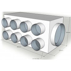
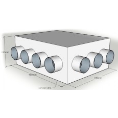
When planning the wiring, consider the noise levels in the house. The star-shaped system with distribution box and flexible pipes (max. length 15 m and minimum bends) has proven to be the most effective for us in terms of crosstalk. More about types of divorces in the article here .
Piping between muffler and junction box:
Choose the pipe according to the location and length. For easily accessible places and short lines, it is possible to use the SONO system, if the pipe runs above the soffit or in an otherwise inaccessible place, choose a solid pipe that can be cleaned in the future with brushes, such as SPIRO . As a flexible option, we recommend the Masterflex pipe.
Distribution (distribution) box:
Plan the distribution box in a place that will be easy to service and the service hole in the ceiling will not be so aesthetically pleasing.
The ideal location is in a technical room without a suspended ceiling or with a coffered plasterboard ceiling. The position of the box must also be chosen taking into account the length of the pipe 90 or 75 mm. These branches should not be longer than 12-15 m, so as not to cause a large pressure loss in the system.
Have the distribution box made to measure or choose one from the prefabricated ones that fits really well. Boxes with pipe openings facing each other, which transmit noise from room to room, are unsuitable. An improperly used box unnecessarily increases the pressure losses of distributions and can cause noisy turbulence. Always order the box with sufficient time reserve. Before ordering, think about how you will attach the box to the structure - galvanized sheet metal boxes weigh several kg. Install the junction box first.
We recommend equipping the distribution box with:
a) service opening
b) hygienic noise insulation, which functions as an additional noise absorber
c) in case of need and good access to the control flaps on the pipe (there must be service access to them)
Piping between the distribution box and the outlet
We offer a choice of 75 mm and 90 mm pipe system.
We use 75 mm most often, it has a larger selection of components, does not take up so much space, offers easy handling and is noise and pressure adequate to supply 30 m3/h of air for one person with one hose.
The system of hoses with an outer diameter of 90 mm can bring more air with one hose (up to 40 m3/h), the unit overcomes the lower pressure resistance of the distributions (pressure loss), so it can behave more quietly and consume less watts. However, indoor noise exposure is usually dependent on the valve used rather than the pipe size (75 or 90 mm).
The pipe must be thoroughly anchored (at least 1.5 m) so that it does not sag or come into contact with the plasterboard or the supporting grid.
Ceiling box ( 75 mm or 90 mm )
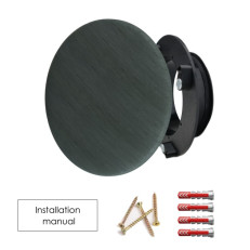
At the end of the pipe there is usually a so-called ceiling box . It is mostly made of plastic. There are several types on the market today. For the 75 mm system, boxes with one or two inlets (1x75 or 2X75 mm) are usually used, the opening for the valve is usually 125 mm.
Some boxes are anchored to the supporting structure and their tube passes through the plasterboard into the interior. The tube is shortened as needed (e.g. OVA ceiling box ) - for these boxes, it is necessary to measure the correct position of the box before installing plasterboards.
The second type of ceiling boxes is anchored in the rough construction phase approx. 1 m from the future position of the outlet. When installing plasterboard, it is necessary to pay attention to the position of the grids and to allow the box to be pulled freely into its final position through the opening. In it, the ceiling box is anchored with a screw that passes through the so-called valve socket, plasterboard and the collar of the ceiling box. GTX boxes are a typical representative.
Most ceiling boxes can also be used without problems, e.g. in partitions made of plasterboard.
We distinguish between ceiling, wall and floor outlets.
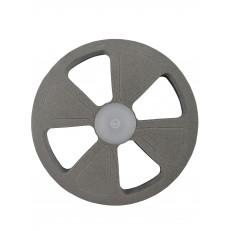
Ceiling outlets (valves)
If the outlet is in the ideal position (i.e. the inlet as far as possible from the outlet or from the entrance to the room and the outlet in the center of the extracted room), any ceiling outlet/valve of the correct size can be used (up to 60 m3/h size 125mm).
For children's rooms, where the layout can often change, we recommend directional valves (e.g. LUFTOMET SKY or BDOP ), which can be used to influence the direction of the air flow into the room.
Wall outlets
If the installation is limited, for example, by the height of the ceiling, a ceiling made of exposed concrete, etc., the outlets can also be installed in the upper part of the wall. In these cases, it is often necessary to influence the direction and reach of the fresh air flow (so that a so-called short circuit does not occur and the fresh air does not leave the room before it is ventilated or diluted by the existing air). For this purpose, so-called nozzles are used, which usually have small holes that increase the speed of the air, as well as its range.
The disadvantage of nozzles in these ventilation systems of family houses is:
a) Insufficient range - the system is often operated at a lower speed and the range is then not according to the project.
b) Higher flow velocity increases noise exposure
We recommend carefully considering the use of nozzles. The solution can be, for example, the installation of a plasterboard box, e.g. with LED lighting along the wall, and place a ceiling outlet in it. However, we have done dozens of installations with a wall solution, and satisfied owners no longer even know where the air is coming from.
Most of the time, the effort is to place the pipe in the next room as high as possible, and the outlet then comes out relatively close to the ceiling. For these installations, we recommend a more angular nozzle (e.g. LUFTOMET JET or WDZA ) from an aesthetic point of view.
Floor outlets (for supply only)
In general, we do not see any advantages in distributions in the floor compared to the previous two variants, and we generally do not recommend them to our clients.
Reasons:
- pipelines in the ground floor are usually at the expense of the height of the thermal insulation on the first floor, then at the expense of the step insulation
- replacement, repair, etc. of pipes is very expensive compared to solutions in suspended ceilings
- outlets in the floor limit the unlimited use of the entire room – positions of furniture, tables, carpets, etc.
- dirt can fall into the nozzles and thus into the system, and they attract playful children like a magnet
- even if the outlets are walkable, injuries can occur
- outlets for air extraction must be installed under the ceiling anyway, so false ceilings or plasterboard boxes cannot be avoided.
If you have any questions or want to advise on something, do not hesitate to contact us.
We offer basic solution designs free of charge, an authorized projection of air-conditioning systems , and we will ensure the installation of the units by persons with service and assembly authorization.
If you want to know more, read other articles of our advice .
THE ARTICLE WAS LAST EDITED ON 7/8/2019

