We are testing
Testing distribution boxes for recuperation vol. #1
Are you also interested in how the air actually moves in the distribution box? What is its ideal shape? How much air goes into each outlet?
Introduction:
You don't read much about distribution (sometimes also called distribution or distribution) boxes in specialist literature. The box is usually used to divide the air behind the unit from a larger pipe diameter (mostly according to the Ø of the recovery unit throat 125, 160 or 200 mm) into several smaller plastic pipes Ø 75 or 90 mm . Flexible pipes then distribute the air to the individual rooms. We have already written several articles about the advantage of this system (see the Luftuj consultancy ).
Simulation or laboratory testing is expensive and can only be done for a select few boxes. According to our experience, there is no universal box that can be used in all types of family houses. And even if it existed, it would be so universal that apparently no one would be able to ensure the measurement of all possible variants (blinding of throats, etc.). That's why we decided to offer individual solutions a few years ago.
We design boxes based on our assembly and service experience. In order not to rely only on empiricism, we decided to test several box variants, the results of the first testing are presented in this article.
Please note that this is testing in a non-certified laboratory, so the results must be taken with a grain of salt.
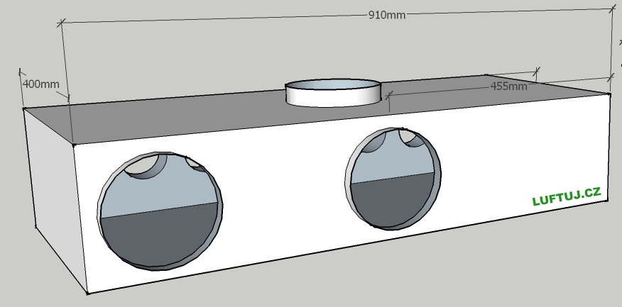
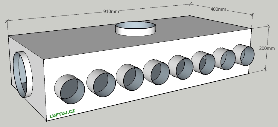
Test box:
Material: Galvanized sheet
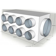
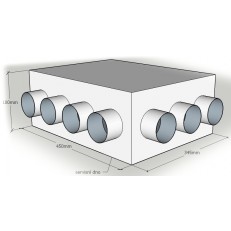
Entrance: 160 mm
Output: 8x75 mm
Dimensions:
Other material used for testing:
Fan: TD 500/160 Ecowatt IP44 energy saving fan
Extension pipe to the throat behind the fan (simulation of intake into the unit):
Material: SPIRO 160 MM
Length: 0.4 m
Silencer between fan and box (traditional solution):
Material: SONOEXTRA 160 MM
Length: 1 m, in some variants it is bent to a right angle
Extension pipe behind the junction box:
Material: MAT STANDARD 75/61 MM
Length: 1 m
Ambient conditions:
Room: closed 10x6m
Temperature: 15°C
Measuring devices:
Anemostat: Testo 405
Test methods:
Test Method #1:
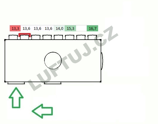
The air flow rate was measured at the end of a 1 m long MAT STANDARD 75/61 mm pipe. The values were measured twice, at the center of the pipe. According to the measured values at the other points, a 1 m long pipe could be considered long enough for steady flow. The resulting value was calculated from the measured values using the arithmetic mean. Due to the different pressure losses of the individual variants, the result is interpreted in % for each tested variant of the box independently.
Test Method #2:
The suction flow rate was measured at the air inlet to the SPIRO at five defined points, from which the resulting value was calculated using an arithmetic mean. The results are interpreted as m/s, and at least proportionally different pressure losses of the assembly (muffler + box) can be derived from them.
Results of individual variants:
Test method #1 in a larger and clearer overview here:
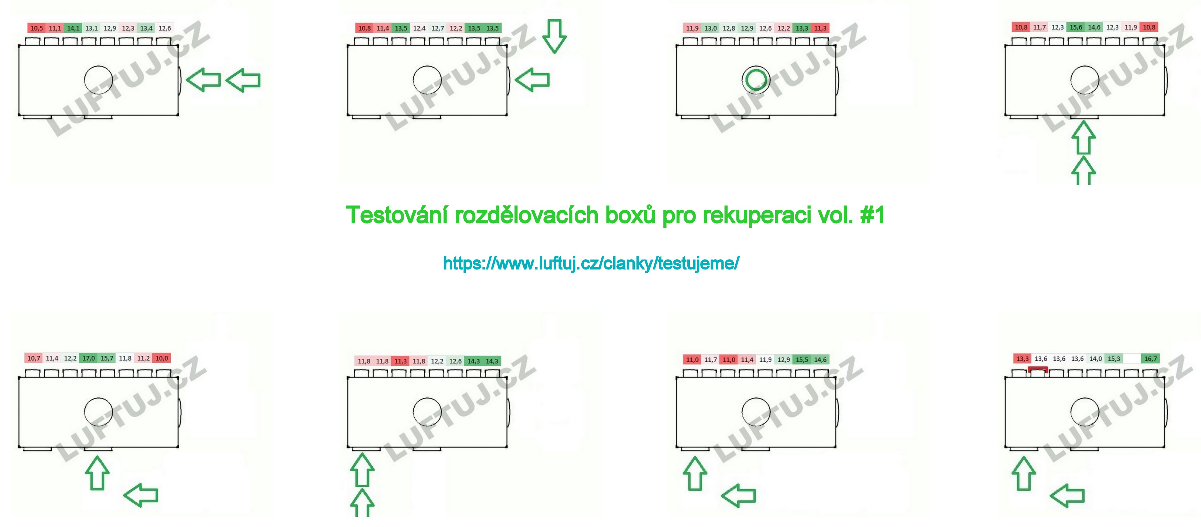
Test method #1 and #2 by individual variants:
Option 1:
Suction: 8.7 m/s
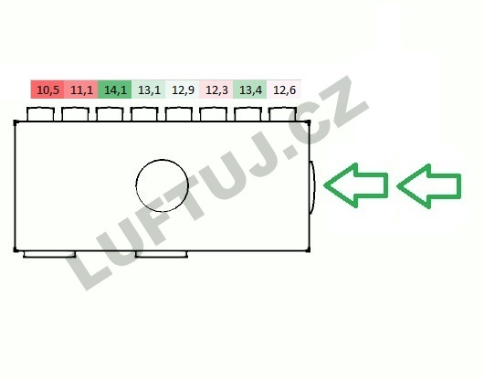
Option 2:
Suction: 8.8 m/s
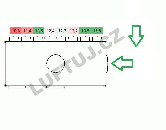
Option 3:
Suction: 8.7 m/s
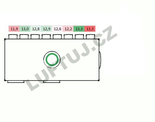
Option 4:
Suction: 8.6 m/s
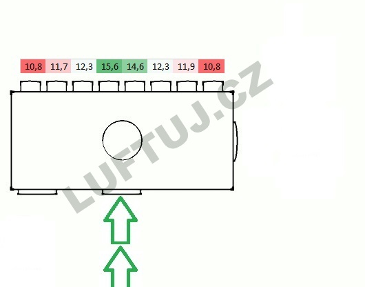
Option 5:
Suction: 8.2 m/s
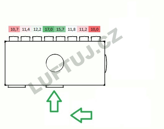
Option 6:
Suction: 8.8 m/s
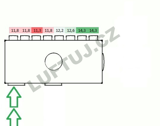
Option 7:
Suction: 8.2 m/s
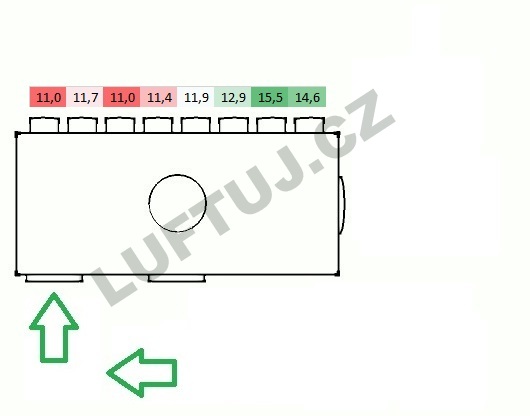
Option 8:
Suction: 8.1 m/s
Conclusion:
The measurement results prove that the differences in air flow in the individual hoses are not large. The largest measured deviation was for variation No. 5. It accounted for 7% of the difference. Which in a real environment with an air flow from the unit of 240 m3/h, can be approx. 17 m3/h. For most other variants, the deviation was around 3%, which means a deviation of approx. 7 m3/h between the "strongest" and "weakest" branches. According to our experience, these deviations can be regulated relatively well at the end outlet.
From the results of measuring the speed of suction into the SPIRO pipeline, it can be concluded that systems where the muffler is bent at a right angle in front of the distribution box and the air flow is directed perpendicularly to the longer side of the box show a greater pressure loss.
Of the other measured values, which we are keeping as a company secret for the time being, we will probably only reveal that with the pipe extension of 75 mm, the deviations of test method No. 1 decrease even more. Furthermore, we filmed and observed the movement of air in the box. We have discovered some "dead spots" where dust can accumulate, etc.
Thanks to the knowledge of the results from this small test, we can now better define and optimize the shape of the boxes and, for example, decide to which neck it is suitable to connect a longer pipe.
For the Lufťák team, she processed:
Ing. Pavla Zavoralová

